STORMTECH SC-310
REQUIRED MATERIALS AND EQUIPMENT LIST
- Acceptable fill materials per the Acceptable Fill Materials Section
- ADS PLUS and non-woven geotextile fabrics
- StormTech solid end caps and pre-cored end caps
- StormTech chambers, manifolds and fittings
IMPORTANT INFORMATION
IMPORTANT NOTES:
A. This installation guide provides the minimum requirements for proper installation of chambers. Non-adherence to this guide may result in damage to chambers during installation. Replacement of damaged chambers during or after backfilling is costly and very time consuming. It is recommended that all installers are familiar with this guide, and that the contractor inspects the chambers for distortion, damage and joint integrity as work progresses.
B. Use of a dozer to push embedment stone between the rows of chambers may cause damage to chambers and is not an acceptable backfill method. Any chambers damaged by using the “dump and push” method are not covered under the Storm Tech standard warranty.
C. Care should be taken in the handling of chambers and end caps. Avoid dropping, prying or excessive force on chambers during removal from pallet and initial placement.
ADS “Terms and Conditions of Sale” are available on the ADS website, www.ads-pipe.com. Advanced Drainage Systems, the ADS logo, and the green stripe are registered trademarks of Advanced Drainage Systems, Inc. StormTech® and the Isolator® Row are registered trademarks of StormTech, Inc.
Call StormTech at 888.892.2694 for technical and product information or visit www.stormtech.com
REQUIREMENTS FOR SYSTEM INSTALLATION
Excavate bed and prepare subgrade per engineer’s plans.
Place non-woven geotextile over prepared soils and up excavation walls. Install underdrains if required.
Place clean, crushed, angular stone foundation 6” (150 mm) min. Compact to achieve a flat surface.
MANIFOLD, SCOUR FABRIC AND CHAMBER ASSEMBLY
Install manifolds and lay out ADS PLUS fabric at inlet rows [min. 12.5 ft (3.8 m)] at each inlet end cap. Place a continuous piece along entire length of Isolator® PLUS Row(s).
Isolator Row PLUS
Place a continuous layer of ADS PLUS fabric between the foundation stone and the Isolator Row PLUS chambers, making sure the fabric lays flat and extends the entire width of the chamber feet. Drape a strip of ADS non-woven geotextile over the row of chambers (not required over DC-780). This is the same type of non-woven geotextile used as a separation layer around the angular stone of the Storm Tech system.
Align the first chamber and end cap of each row with inlet pipes. Contractor may choose to postpone stone placement around end chambers and leave ends of rows open for easy inspection of chambers during the backfill process.
Attaching the End Caps
Lift the end of the chamber a few inches off the ground. With the curved face of the end cap facing outward, place the end cap into the chamber’s end corrugation.
Prefabricated End Caps
24” (600 mm) inlets are the maximum size that can fit into a SC-740/DC-780 end cap and must be prefabricated with a 24” (600 mm) pipe stub. SC-310 chambers with a 12” (300 mm) inlet pipe must use a prefabricated end cap with a 12” (300 mm) pipe stub.
Continue installing chambers by overlapping chamber end corrugations. Chamber joints are labeled “Lower Joint – Overlap Here” and “Build this direction – Upper Joint” Be sure that the chamber placement does not exceed the reach of the construction equipment used to place the stone. Maintain minimum 6” (150 mm) spacing between rows
STORMTECH ISOLATOR ROW DETAIL
Figure 1: Inserta Tee Detail
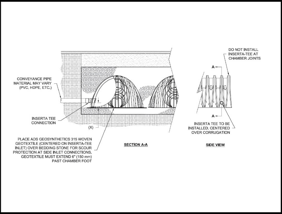
INSERTA TEE FITTINGS AVAILABLE FOR SDR 26, SDR 35, SCH 40 IPS GASKETED & SOLVENT WELD, N-12, HP STORM, C-900 OR DUCTILE IRON
NOTE : PART NUMBERS WILL VARY BASED ON INLET PIPE MATERIALS. CONTACT STORMTECH FOR MORE INFORMATION.
Figure 2: Isolator Row Detail
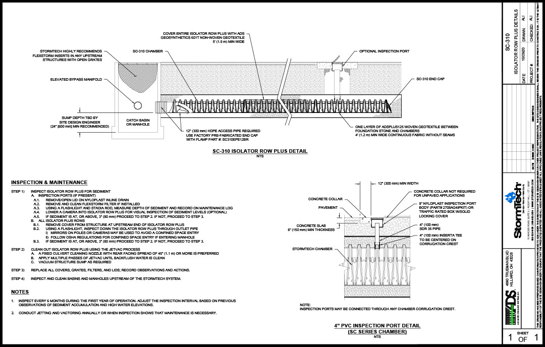
Figure 3: Inspection Port Detail
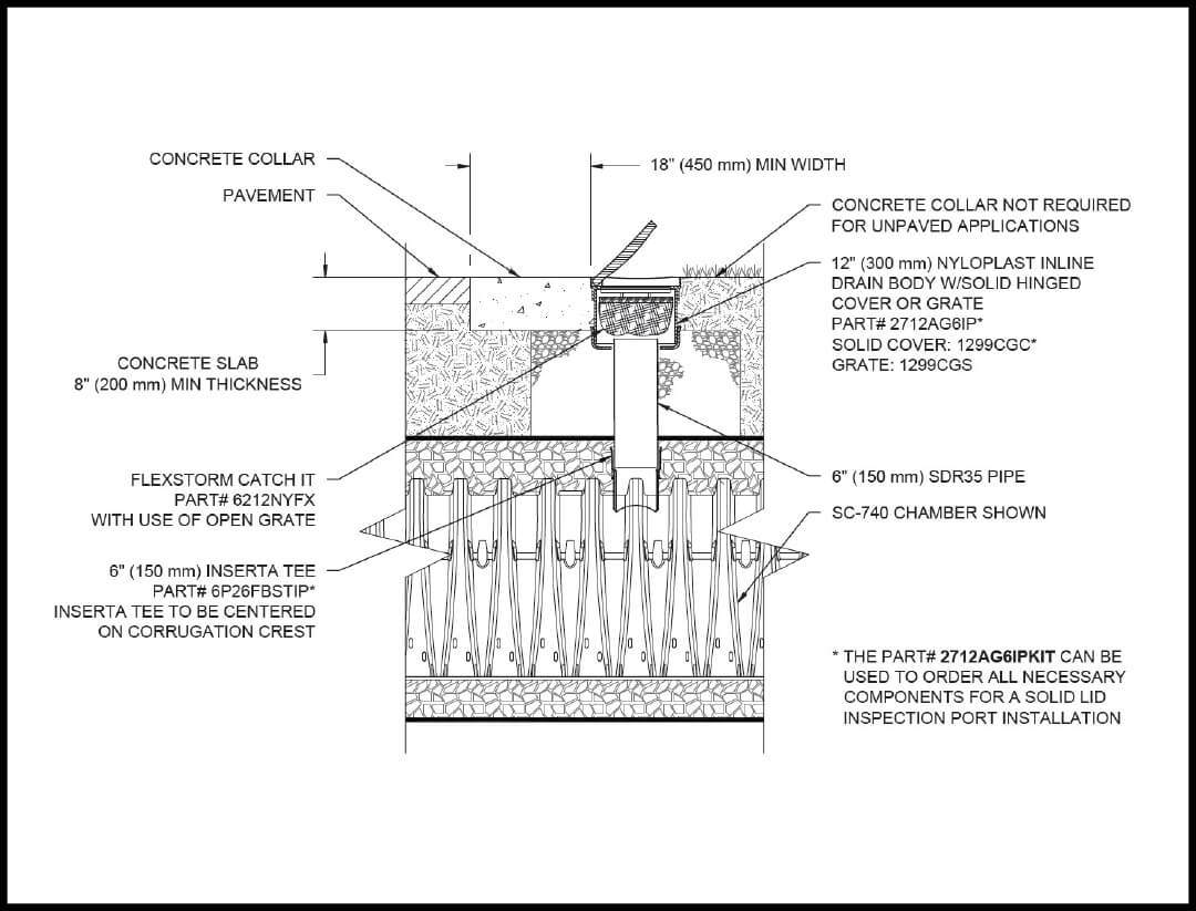
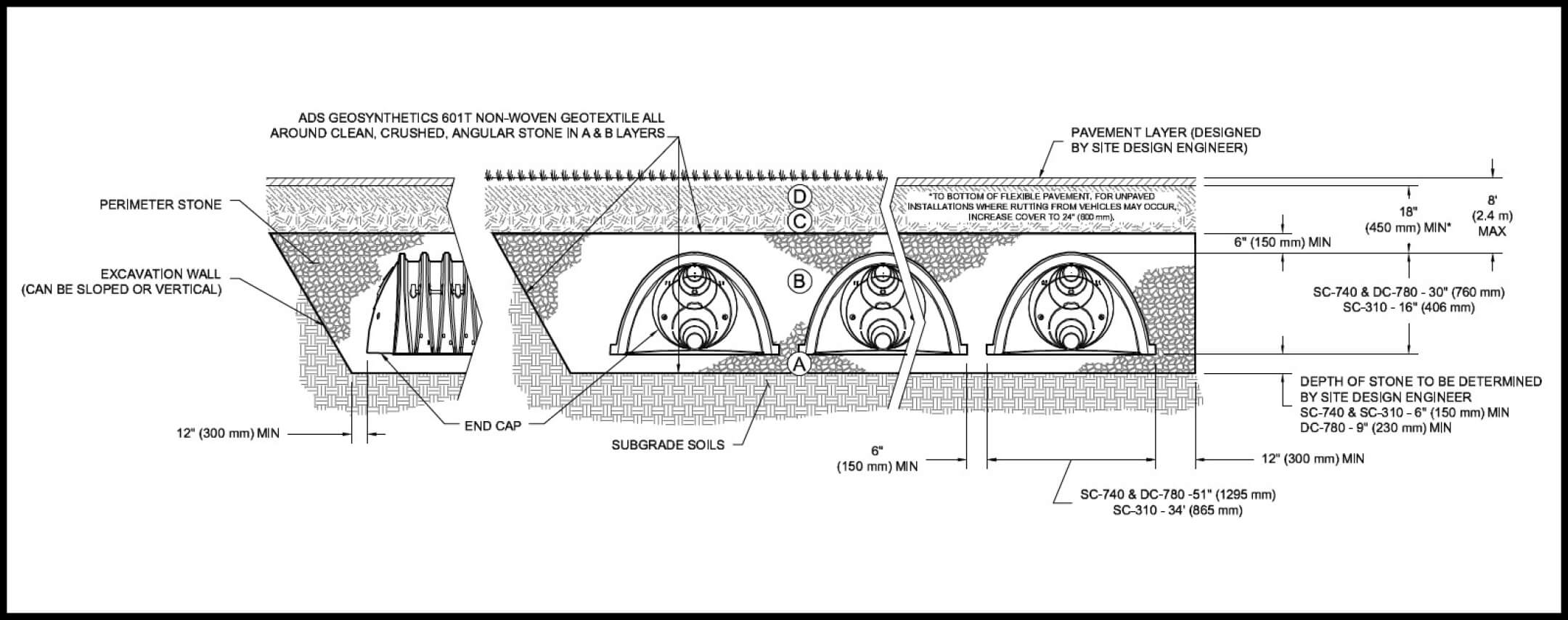
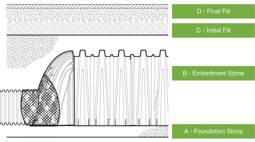
Figure 4: Fill Material Locations
INITIAL ANCHORING OF CHAMBERS - EMBEDMENT STONE
Initial embedment shall be spotted along the centerline of the chamber evenly anchoring the lower portion of the chamber. This is best accomplished with a stone conveyor or excavator reaching along the row.
No equipment shall be operated on the bed at this stage of the installation. Excavators must be located off the bed. Dump trucks shall not dump stone directly on to the bed. Dozers or loaders are not allowed on the bed at this time.
BACKFILL OF CHAMBERS – EMBEDMENT STONE
Backfill chambers evenly. Stone column height should never differ by more that 12″ (300 mm) between adjacent chamber rows or between chamber rows and perimeter.
Uneven Backfill – Incorrect
Even Backfill – Correct
Perimeter stone must be brought up evenly with chamber rows. Perimeter must be fully backfilled, with stone extended horizontally to the excavation wall.
Perimeter Not Backfilled – Incorrect
Perimeter Not Backfilled – Incorrect
BACKFILL OF CHAMBERS – EMBEDMENT STONE AND COVER STONE
Continue evenly backfilling between rows and around perimeter until embedment stone reaches tops of chambers. Perimeter stone must extend horizontally to the excavation wall for both straight or sloped sidewalls. Only after chambers have been backfilled to top of chamber and with a minimum 6” (150 mm) of cover stone on top of chambers can small dozers be used over the chambers for backfilling remaining cover stone.
Small dozers and skid loaders may be used to finish grading stone backfill in accordance with ground pressure limits in Acceptable Fill Materials below. They must push material parallel to rows only. Never push perpendicular to rows. Storm Tech recommends that the contractor inspect chambers before placing final backfill. Any chambers damaged by construction shall be removed and replaced.
FINAL BACKFILL OF CHAMBERS – FILL MATERIAL
Install non-woven geotextile over stone. Geotextile must overlap 24” (600 mm) min. where edges meet. Compact each lift of backfill as specified in the site design engineer’s drawings. Roller travel parallel with rows.
ACCEPTABLE FILL MATERIALS
SELECT A MATERIAL SECTION BELOW TO LEARN MORE
ACCEPTABLE FILL MATERIALS
D- Final Fill
Any soil/rock materials, native soils or per engineer’s plans. Check plans for pavement subgrade requirements.
Fill Material for layer ‘D’ starts from the top of the ‘C’ layer to the bottom of flexible pavement or unpaved finished grade above. Note that the pavement subbase may be part of the ‘D’ layer.
AASHTO M43 Designation*
N/A
Compaction/Density Requirement
Prepare per site design engineer’s plans. Paved installations may have stringent material and preparation requirements.
(Table 1D)
Wheel Loads
| Fill Depth Over Chambers in. [mm] | Max Axle Load For Trucks lbs [kN] | Max Wheel Load for Loaders lbs [kN] |
|---|---|---|
| 36” [900] Compacted | 32,000 [142] | 16,000 [71] |
36” (900 mm) minimum cover required for dump trucks to dump over chambers.
Track Loads
| Fill Depth Over Chambers in. [mm] | Track Width in. [mm] | Max Ground Pressure psf [kPa] |
|---|---|---|
| 36” [900] Compacted | 12” [305] | 3420 [164] |
| 18” [457] | 2350 [113] | |
| 24” [610] | 1850 [89] | |
| 30” [762] | 1510 [72] | |
| 36” [914] | 1310 [63] |
Dozers to push parallel to rows until 36” (900mm) compacted cover is reached4.
Roller Loads
| Fill Depth Over Chambers in. [mm] | Max Drum Weight or Dynamic Force lbs [kN] |
|---|---|
| 36” [900] Compacted | 38,000 [169] |
| 24” [600] Loose/Dumped | 16,000 [71] |
| 18” [450] | 5,000 [22] (static loads only)5 |
Roller travel parallel to rows only until 36” (900 mm) compacted cover is reached.
PLACEMENT METHODS/RESTRICTIONS
A variety of placement methods may be used. All construction loads must not exceed the maximum limits listed above.
(Table 3D)
ACCEPTABLE FILL MATERIALS
C- Initial Fill
Granular well-graded soil/aggregate mixtures, <35% fines or processed aggregate. Most pavement subbase materials can be used in lieu of this layer..
Fill Material for layer ‘C’ starts from the top of the embedment stone (‘B’ layer) to 18” (450 mm) above the top of the chamber. Note that pavement subbase may be part of the ‘C’ layer.
AASHTO M43 Designation*
AASHTO M45 A-1, A-2-4, A-3 or AASHTO M431 3, 357, 4, 467, 5, 56, 57, 6, 67, 68, 7, 78, 8, 89, 9, 10
Compaction/Density Requirement
Begin compaction after min. 12” (300 mm) of material over the chambers is reached. Compact additional layers in 6” (150 mm) max. lifts to a min. 95% Proctor density for well-graded material and 95% relative density for processed aggregate materials. Roller gross vehicle weight not to exceed 12,000 lbs (53 kN). Dynamic force not to exceed 20,000 lbs (89 kN).
(Table 1C)
MAXIMUM CONSTRUCTION LOADS6
Wheel Loads
| Fill Depth Over Chambers in. [mm] | Max Axle Load For Trucks lbs [kN] | Max Wheel Load for Loaders lbs [kN] |
|---|---|---|
| 24” [600] Compacted | 32,000 [142] | 16,000 [71] |
| 24” [600] Loose/Dumped | 32,000 [142] | 16,000 [71] |
| 18” [450] | 32,000 [142] | 16,000 [71] |
Asphalt can be dumped into paver when compacted pavement subbase reaches 18” (450 mm) above top of chambers.
Track Loads
| Fill Depth Over Chambers in. [mm] | Track Width in. [mm] | Max Ground Pressure psf [kPa] |
|---|---|---|
| 24” [600] Compacted | 12” [305] | 2480 [119] |
| 18” [457] | 1770 [85] | |
| 24” [610] | 1430 [68] | |
| 30” [762] | 1210 [58] | |
| 36” [914] | 1070 [51] | |
| 24” [600] Loose/Dumped | 12” [305] | 2245 [107] |
| 18” [457] | 1625 [78] | |
| 24” [610] | 1325 [63] | |
| 30” [762] | 1135 [54] | |
| 36” [914] | 1010 [48] | |
| 18” [450] | 12” [305] | 2010 [96] |
| 18” [457] | 1480 [71] | |
| 24” [610] | 1220 [58] | |
| 30” [762] | 1060 [51] | |
| 36” [762] | 950 [45] |
Small LGP track dozers & skid loaders allowed to grade cover stone with at least 6” (150 mm) stone under tracks at all times. Equipment must push parallel to rows at all times.
Roller Loads
| Fill Depth Over Chambers in. [mm] | Max Drum Weight or Dynamic Force lbs [kN] |
|---|---|
| 24” [600] Compacted | 20,000 [89] |
| 24” [600] Loose/Dumped | 20,000 [89] Roller gross vehicle weight not to exceed 12,000 lbs. [53 kN] |
| 18” [450] | 20,000 [89] Roller gross vehicle weight not to exceed 12,000 lbs. [53 kN] |
Use dynamic force of roller only after compacted fill depth reaches 12” (300 mm) over chambers. Roller travel parallel to chamber rows only.
PLACEMENT METHODS/RESTRICTIONS
Excavator positioned off bed recommended. Small excavator allowed over chambers. Small dozer allowed.
(Table 3C)
B – Embedment Stone
Clean, crushed, angular stone
Embedment Stone surrounding chambers from the foundation stone to the ‘C’ layer above.
Minimum 6″ (150 mm) cover stone on top of chamber.
AASHTO M43 Designation*
AASHTO M43 – 3, 357, 4, 467, 5, 56, 57
Compaction/Density Requirement
No compaction required.
(Table 1B)
MAXIMUM CONSTRUCTION LOADS6
Wheel Loads
| Fill Depth Over Chambers in. [mm] | Max Axle Load For Trucks lbs [kN] | Max Wheel Load for Loaders lbs [kN] |
|---|---|---|
| 12” [300] | 16,000 [71] | NOT ALLOWED |
| 6” [150] | 8,000 [35] | NOT ALLOWED |
No wheel loads allowed. Material must be placed outside the limits of the chamber bed.
Track Loads
| Fill Depth Over Chambers in. [mm] | Track Width in. [mm] | Max Ground Pressure psf [kPa] |
|---|---|---|
| 12” [300] | 12” [305] | 1540 [74] |
| 18” [457] | 1190 [57] | |
| 24” [610] | 1010 [48] | |
| 30” [762] | 910 [43] | |
| 36” [762] | 840 [40] | |
| 6” [150] | 12” [305] | 1070 [51] |
| 18” [457] | 900 [43] | |
| 24” [610] | 800 [38] | |
| 30” [762] | 760 [36] | |
| 36” [762] | 720 [34] |
No tracked equipment is allowed on chambers until a min. 6” (150 mm) cover stone is in place.
Roller Loads
| Fill Depth Over Chambers in. [mm] | Max Drum Weight or Dynamic Force lbs [kN] |
|---|---|
| 12” [300] | 20,000 [89] Roller gross vehicle weight not to exceed 12,000 lbs. [53 kN] |
| 6” [150] | NOT ALLOWED |
No rollers allowed.
PLACEMENT METHODS/RESTRICTIONS
No equipment allowed on bare chambers. Use excavator or stone conveyor positioned off bed or on foundation stone to evenly fill around all chambers to at least the top of chambers.
Minimum 6″ (150 mm) cover stone on top of chamber.
(Table 3B)
ACCEPTABLE FILL MATERIALS
A – Foundation Stone
Clean, crushed, angular stone
Fill below chambers from the subgrade up to the foot (bottom) of the chamber.
AASHTO M43 Designation*
AASHTO M43 – 3, 357, 4, 467, 5, 56, 57
Compaction/Density Requirement
Place and compact in 6” (150 mm) lifts using two full coverages with a vibratory compactor.**, ***
(Table 1A)
PLACEMENT METHODS/RESTRICTIONS
No StormTech restrictions. Contractor responsible for any conditions or requirements by others relative to subgrade bearing capacity, dewatering or protection of subgrade.
(Table 3A)
PLEASE NOTE:
*. The listed AASHTO designations are for gradations only. The stone must also be clean, crushed, angular. For example, a specification for #4 stone would state: “clean, crushed, angular no. 4 (AASHTO M43) stone”.
**. StormTech compaction requirements are met for ‘A’ location materials when placed and compacted in 6” (150 mm) (max) lifts using two full coverages with a vibratory compactor.
***. Where infiltration surfaces may be comprised by compaction, for standard installations and standard design load conditions, a flat surface may be achieved by raking or dragging without compaction equipment. For special load designs, contact StormTech for compaction requirements.
1. 36” (900 mm) of stabilized cover materials over the chambers is required for full dump truck travel and dumping.
2. During paving operations, dump truck axle loads on 18” (450 mm) of cover may be necessary. Precautions should be taken to avoid rutting of the road base layer, to ensure that compaction requirements have been met, and that a minimum of 18” (450 mm) of cover exists over the chambers. Contact StormTech for additional guidance on allowable axle loads during paving.
3. Ground pressure for track dozers is the vehicle operating weight divided by total ground contact area for both tracks. Excavators will exert higher ground pressures based on loaded bucket weight and boom extension.
4. Mini-excavators (<8,000lbs/3,628 kg) can be used with at least 12” (300 mm) of stone over the chambers and are limited by the maximum ground pressures in Table 2 based on a full bucket at maximum boom extension.
5. Storage of materials such as construction materials, equipment, spoils, etc. should not be located over the StormTech system. The use of equipment over the StormTech system not covered in Table 2 (ex. soil mixing equipment, cranes, etc) is limited. Please contact StormTech for more information.
6. Allowable track loads based on vehicle travel only. Excavators shall not operate on chamber beds until the total backfill reaches 3 feet (900 mm) over the entire bed.